REFURBISHING THE NAUTILUS MINISUB
PAGE FIVE

If
this is your first visit,
you
might want to scroll to the bottom and click PREVIOUS to access earlier
pages. There's four before this one.
~Otherwise~
SCROLL DOWN FOR THE LATEST
J
Wednesday, March 27, 2019: Refurbishing
4 became large and slow to load so
I've started Refurbishing 5.
NAUTILUS MINISUB
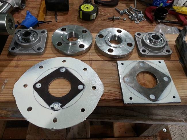
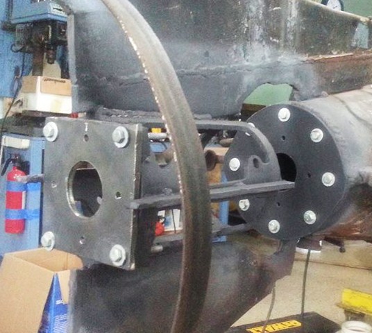
DRIVETRAIN: The blue cast-iron flange bearings shown on the previous page are
for setup and testing purposes only. For
the actual installation I bought a pair of these stainless steel flange
bearings. This way the entire drivetrain is stainless steel; bearings included. Better longevity in seawater than cast
iron.
7/8" ID Stainless
Steel four-bolt flange bearing.
Sunday, March 31, 2019:
Lots of work this past week; check THE CLIPBOARD for more info.
Last night I did this
diagram of the pressure compensated propeller shaft housing / manifold with a cutaway showing the
internal carbon-ceramic shaft seal.
Simple drawings like this help me in the design process. I'm not going to win any drafting
competitions but they help me check the fit of component parts before I order
them or they arrive by mail. This is
what we did before we had CAD, kids! J
The mottled black /
gray represents the submarine's pressure hull, fins, and rudder. The blue is water and the white is inside the
pressure hull; dry at 1 atmosphere pressure.
The prop is yellow because it's brass.
The cap nut and two of the flanges are chrome but everything shaded with
gray pencil is stainless steel.
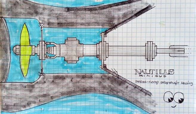
(From left to right:
RUDDER; PROPSHAFT CAP NUT; WASHER; PROPELLER; COLLAR; SHAFT; BEARING; 1/4"
AFT BEARING MOUNTING PLATE; FLANGE; REDUCER BUSHING; INTERNAL SHAFT SEAL;
CUTAWAY BELL REDUCER; CLOSE NIPPLE; CROSS-TEE WITH REDUCER; NIPPLE; FLANGE;
1/4" BULKHEAD; FLANGE; NIPPLE; FLANGE; BEARING; SHAFT; COUPLING TO GEAR
REDUCER AND MOTOR.)
All of the parts for
this manifold are in the mail and arrive next week; should be able to start
assembly and testing soon. Film at eleven. J
UPDATE, TODAY: Here's
another example of how a pad and pen aid my design process. This is my new bilge sump pump and tank
schematic. By controlling the valves, I
can either pump the bilge overboard when running surfaced; or to a storage tank
from whence it can be pressure-purged overboard while submerged. You don't have to get fancy. At this point; simple sketches like this are
all it takes.
Easily over 98% of
the prospective subbers I've talked to get what I
call "analysis paralysis";
they never get past the design phase.
For them, being a subber means being part of a
discussion group and sharing pictures and conjecture with others on that same
level. They are just playing with their
computers and they never get to the point of cutting steel. Analysis paralysis.
I'm exactly the
opposite. Simple concept schematics,
graph paper drawings, and templates are all I need to produce steel parts from
which I build submarines. I prefer to
spend minimal time drawing and maximum time fabricating. In contrast with others, I guess you could
say I have "fabrication motivation."
Works for me. J
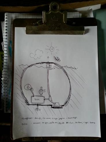
Crude initial bilge pump
system concept diagram.
Even so, I still generate boxes of drawings
and research notes on a project like this; some basic and some more refined;
whatever's needed at the time. Here's a
look at what I've generated in the past several weeks working on the drivetrain, bench test setup, guidance control
through-hulls, 12V electrical accessories system, and now the bilge pumping
system. Every idea that occurred to
me; everything I need to buy, make, or otherwise acquire; and how I was going
to proceed is all documented in pages like these.
People say they
"can't imagine what it takes" to do something like this. For me, working under these conditions, this
is a big part of it.
Conceiving,
designing, and building a submarine is a lot of work, but I don't feel as
though I've "got" to do it; I feel like I "get" to do
it. When you love what you do; it's not
really work. J
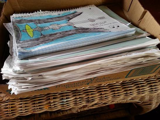
R&D notes.
Wednesday, April 03, 2019: TEST BENCH: salvaged an old 3x9' sheet of
siding from which I'll cut a 2.5 x 6' base plate for the test bench; cleaned it
up and laid it out to dry. Also got the
10' 2X10" mounting board ready to go.
Still have to buy a 4x8' sheet of plywood to make the water tank.
DRIVETRAIN: The
propeller shaft went to the Machine shop on Monday and might be done tomorrow,
but you NEVER rush a machinist. J
Needed a few more
parts for the propshaft housing / manifold; they are
in the mail and some actually arrived today.
No unusual delays there.
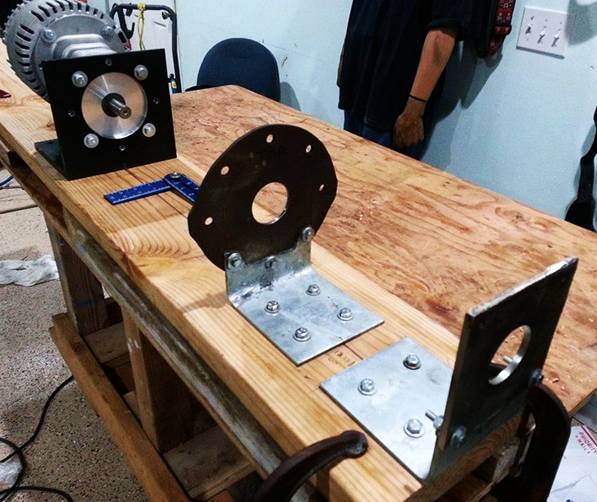
Bought some heavy
duty brackets at Home Depot (to support the propshaft
bearings on the test bench) that were $30 each and the quality sucked. Taking them back for a refund. But first, I've used them as templates on a piece of 6"
x 6" square tube and I'll cut and drill my own brackets to fit the
bearings and flanges precisely.
The thing about
making these brackets is the propshaft height above
the 2x10" base board must be exactly the same from the motor through two
brackets and bearings, and to the propeller.
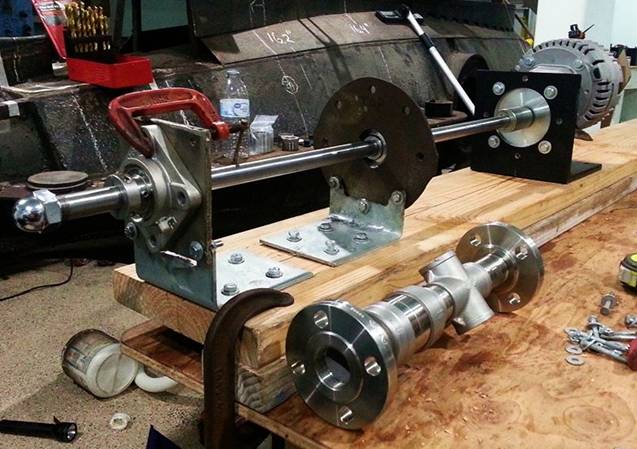
I tried guestimation and then got a better
idea. I cannibalized an old 7/8"
drill bit; chucked it up in the drivetrain shaft coupler;
positioned the template-marked bracket stock in front of the bit; and spun the
motor.
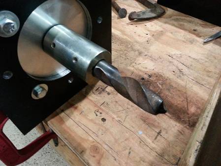
An old 7/8" drill
bit; shortened, sanded, and secured in the propshaft
coupler; to be used as a drill.
The intent was to
determine exactly where the center of the propshaft
will be when motor is mounted on its mount and the propshaft
bearings are mounted on 6" brackets atop a spacer made from a 1.5"
thick piece of 2x10" lumber.
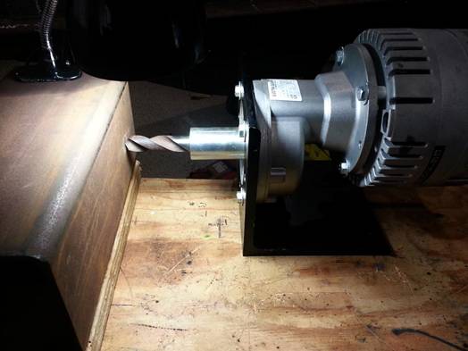
ME1117 and Gear Reducer
driving 7/8" drill bit to mark centerline on mounting bracket stock.
In this pic you can see the guesstimation
marks I made with a scribe, using one of the bearings as a guide. Didn't measure anything; just eyeballed
it. The little round circle near the
center of the X is the actual centerpoint for the propshaft. (Drill
bit was junk.) I would have only been
off by a 16th of an inch, but when you're talking about something that's heavy and spinning at thousands of RPM; even
that small variance is unacceptable if I can prevent it.
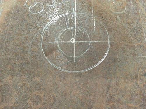
"Best-guess"
scribe marks and actual center of drive train comparison.
Next, I'll put that
piece on the drill press and that's where the pilot bit of my carbide hole saw will go. Once I have drilled a nice 7/8" hole, I
can position the flange, bearing,and shaft to
precisely mark where all the bolt holes must go. Easy peasy! J
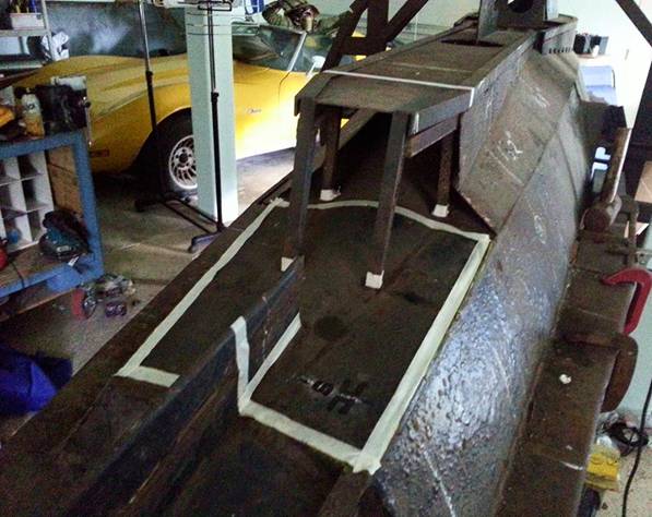
TEST BENCH WITH WATER
TANK: Here's a crude drawing of what I'm building: its
based on a 2X10; has a 2X2' water chamber around the prop and manifold. The MOON EYES are a "note to self"
to notice something on this page. Here,
it was that I'd decided to eliminate the 1/2" neoprene pads I've presently
used under the motor mount.
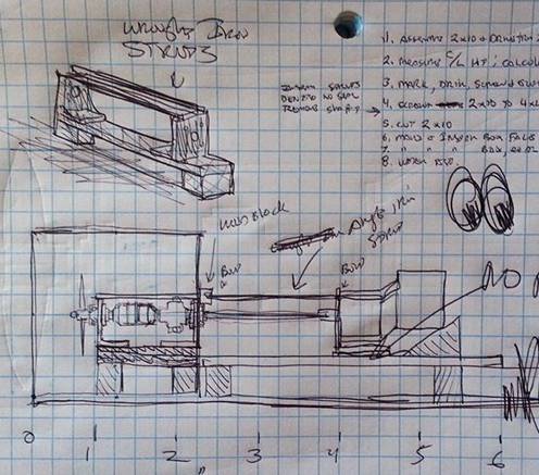
Basic schematic for test
bench / water tank; showing manifold, mounts, motor, and struts.
I know from past experience:
bolting everything down securely and minimizing chances for vibration are
critical. Not only will I not be using
rubber pads under the motor mount; I'm
making struts of angle iron that will be welded onto the top of the manifold
brackets and bolted from the forward bracket to the already drilled-and-tapped
motor mount. It's not enough for the
mounts to be fastened to the foundation; the tops of the mounts must be rigidly
connected to prevent them from flexing fore and aft under load, when things get
spinning and it all gets crazy. J
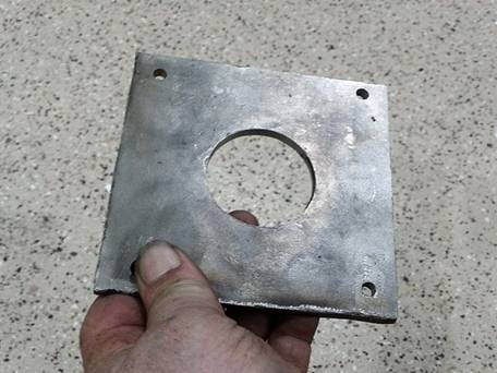
Saturday, April 06, 2019:
Got the basic drivetrain running on one bracket and
bearing last night. I used the old tailcone plate because it's already sized and drilled to
match the tailcone bulkhead boss. I roughed out a bracket to position the tailcone plate in alignment with the gear reducer output
shaft. Marked the center point and
drilled a 2" hole with my carbide hole saw. Worked fine.
I have to make one
more like this out of mild steel; about 5" square to serve as the
propeller bearing mounting bracket. Once
I have it all worked out, these old 3/16" mild steel parts will serve as
templates from which I will make final versions from 1/4" stainless steel.
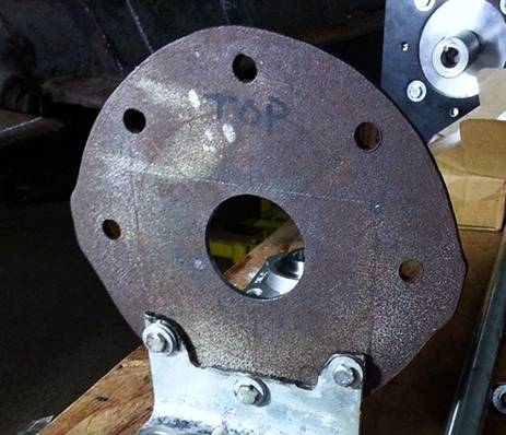
3/16" mild steel
Nautilus Minisub tailcone
bulkhead; circa 1991.
Also, assembled the
propeller shaft housing / manifold and hung it in position with some wire to
check the fit. In this pic it's hand-tightened and still only 3/8" longer
than it needs to be to fit between the tailcone
bulkhead and propellershaft mounting brackets. I won't have any problem getting it to final
fit using a wrench.
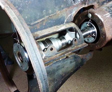
Stainless steel propshaft housing / manifold in position on Nautilus Minisub.
Next, I'll make a
prop bearing mounting plate; attach a bracket so it will bolt onto the bench;
size it next to the gear reducer output shaft, and mark the centerline. Cut a 2" hole around the center point;
insert the shaft, slide the bearing on the shaft up against the plate, mark the
bolt holes, and drill 'em. Once that's done I can bolt the brackets to
the bench; bolt in the manifold, insert the propshaft,
connect to the gear reducer, install the propeller and cap nut, and test it all
for clearance of rotary parts.
If it's okay, I
install the pump seal on the shaft, reassemble the drivetrain
with a temporary water jacket around the pump seal housing vent holes, and wet
test the seal. No leaks? We're ready to put it into the submarine. J
Monday, April 08, 2019: DRIVETRAIN: Had to redesign the propshaft manifold and ordered a new set of flanges over
the weekend.
Built an internal
seat for the carbon ceramic shaft seal; made it out of PVC parts of a swimming
pool pump hose, a rubber hose grommet; and a couple odd pieces of PVC.
Today I made a rudder
bearing mounting plate out of 3/16th mild steel; modified a piece of 6"
angle to support it on the testing bench; aligned it with the gear reducer
output shaft; and set up the basic drivetrain (motor,
gear reducer, L mount, shaft coupling, shaft, tailcone
bearing and mounting plate; propeller bearing and mounting plate; shaft collar;
propeller; cap nut) positioned and held together with a combination of bolts
and clamps.
It turns but I don't
dare run it until I get everything "trued-up and screwed down" as
they say. J
Didn't drill the
bearing mounting plates to receive the bearings yet; waiting until the new
manifold flanges arrive. I believe the
bearings and flanges share a common 4" bolt pattern and I'm hoping to get
by with only one set of four bolt holes per plate.
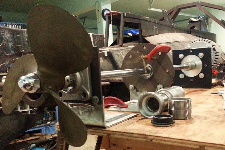
Here's a look at the propshaft sitting in the tailcone
and propeller support bearings. These
old steel parts will serve the bench testing process and become templates from
which I'll make better ones out of stainless steel.
Speaking of stainless
steel; those fittings in the lower right quadrant are the basis for the
manifold now. That white PVC material in
the bell serves as a watertight support for the mechanical shaft seal seat
holder. That black and white rubber
thing in front of the threaded nipple (like a lot of what I do) got cobbled
together from available hardware and parts of other devices adapted to my
purpose. That's been the theme of this
project since day one back in the 1980's.
No great big shop or supply source here; just a shadetree
mechanic making do with what's available.
J
Tuesday, April 09, 2019:
The propshaft manifold flanges don't arrive until
later this week; can't drill the bearing mounting plates until then. Meanwhile, I've laid out the lumber to make
the test bench (this is my workbench) and did a little cleanup work on that
vintage brass propeller. I'm not saying
it would pass Brass Inspection at MCRD San Diego, but ya
gotta admit it does look a little bit better. J
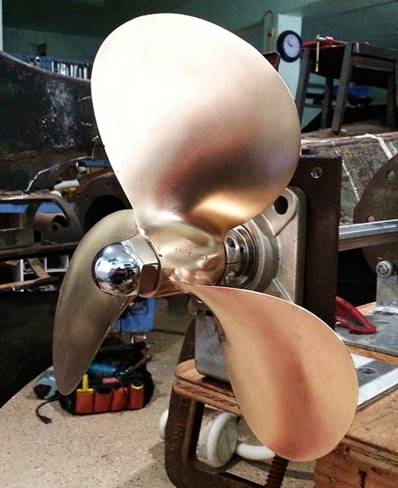
"Hi-Speed" 12
x 13 RH brass propeller
Wednesday, April 17, 2019:
Went around in a couple circles getting the parts together for the propshaft manifold, but this is the final incarnation;
pretty much exactly as originally designed.
The bolt pattern on the bearings and flanges match so I can bolt them to
the tailcone bulkhead and propeller bearing bracket
via the same four shared holes; which is very fortunate (less work) for
me. J
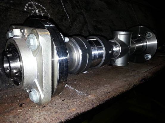
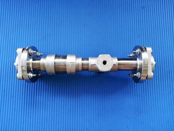
Stainless steel
propeller shaft housing manifold.
Below is another view
of the manifold with the functional areas indicated and explained. A turbine-type high-speed carbon-ceramic
shaft seal is in the bell-chamber and the cross-T will comprise a
pressure-compensated chamber between the seal and the pressure hull / motor
compartment. Between the flanges and
bearings goes the 1/4" stainless steel tailcone
bulkhead and propeller bearing brackets, which bolt to the hull with rubber
gaskets. I have two 1-1/4 to 1/4"
NPT reducer bushings for the cross-T; to which the fittings for the air inlet
and one-way exhaust valve will fit, but they're not shown here. I (at least) need to shorten them for height
clearance and may actually have to weld them in.
I'm confident the
shaft seal will work but have some concerns about whether the pressure in the
air-compensated chamber will defeat the seal.
That's why we're going to put the drivetrain
together on a test bench; wrap a water jacket around the shaft seal chamber
(after we drill some vent holes in the center nipple); and test it for leaks
before it gets installed. If the seal is
as good as I think it will be; might not even need the pressure
compensation. We'll see when the time
comes.
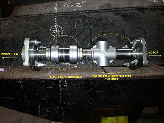
L to R: Bearing; flange;
close 1-1/4" nipple; bell; close 2" nipple; bell; 1-1/4" close
nipple; cross-T; 3" nipple; flange; bearing.
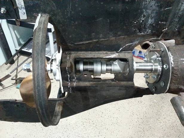
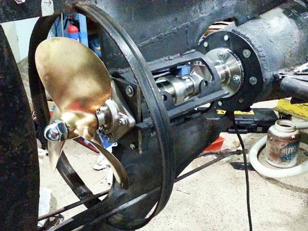
And here's a pic of the manifold sitting in the tailcone
of the submarine. This isn't precise but
it shows about where it will sit when the drivetrain
is operational. And for our new
visitors: yes, the submarine is rusty and dusty. It's all surface rust and that's why they
have sand blasters. J
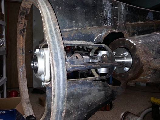
Propshaft manifold positioned in tailcone / motor-mount area of NAUTILUS MINISUB.
I think the visual
contrast between the rusty steel and the stainless manifold is interesting:
depicts this as a vintage (old) homebuilt submersible being refurbished with
new parts and technologies. That's kind
of what this refurbishment is all about.
The NAUTILUS MINISUB is an old warhorse being reborn. When complete, all that "crud of
ages" will be blasted off and she'll receive a new exterior covering of
acrylic resin, acrylic cabochons (rivets), and acrylic enamel paint to
compliment all the beautiful new stuff being installed.
UPDATE TODAY: Here's
better looks at the manifold. I think
this exemplifies the spirit with which I've approached creative technologies
right from the start: "Adapt what's available to accomplish what you
need."
This is a fairly
sophisticated device of my own invention: a propeller shaft housing that combineds a turbine
shaft seal with pressure compensation. Most people would need to have something like
this made for them and/or machined from scratch. I found a way to do it using available
hardware and things laying around my shop.
This is what you call backyard submarine boatyard ingenuity, folks. That's what I'm all about. J
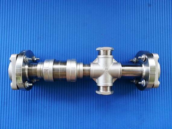
Side elevation view:
NAUTILUS MINISUB propeller shaft manifold.
The fasteners look
long but will come out just right when there's a 1/4" stainless steel
mounting plate and rubber gasket between the outer bearings and flanges. The reducer bushings in the cross-T go down
to 1/4" NPT to accommodate the airline and exhaust valve fittings. The entire assembly (including the plates
that mount it to the submarine) are all stainless steel so there will be
virtually no chance of rust contaminating the mechanical seal or bearings.
Planform view: NAUTILUS MINISUB propeller
shaft manifold.
I want to get the
reducer bushing bosses down flush with the top and bottom of the cross-T. If it gets too tight trying to thread it down
that far; I'll either shorten it and redress the threads or weld the hex head
on. Getting very close to having the drivetrain running on the bench with a functional water
test of the shaft seal. Progress! J
Sunday, April 21, 2019:
As of tonight I have the stainless steel propeller shaft bearing mounting plate
and mild steel tailcone bulkhead on brackets, aligned on and bolted to a 2X10, and I'm
about to secure the motor. Next, I
temporarily install the propellershaft, mark the
holes for the bearing / flange mounting hardware; drill those eight holes and
then I am ready to assemble for bench testing.
Stainless steel
propeller bearing mounting plate. Still
a little cleanup to do.
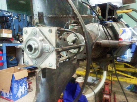
Assembling and aligning
the motor bracket, tailcone bracket, and propeller
mounting bracket on the bench for marking and drilling of bearing / flange bolt
holes.
That little blue tool
is called an OMNISQUARE and was very
helpful in measuring and aligning the brackets on the 2X10.
While the propeller
bearing mounting plate is now stainless steel (to keep rust out of the
mechanical shaft seal chamber) I'll be using the old (mild steel) tailcone bulkhead because (1) I already have it and it's
ready to go; (2) it doesn't touch the shaft seal wet chamber so it can't add
rust to that area; and (3) it connects to the hull (which is mild steel anyway)
so it doesn't make any difference to the system whether this part is mild or
stainless steel. I'll sand blast it,
treat it for rust, and paint it with acrylic enamel before it goes into service
on the submarine.
UPDATE: Tonight I got very close to having it
properly aligned so I can the holes for the bearing mount hardware. Still have a little tweaking to do to the
middle bracket. Working on it. That's the propeller shaft housing manifold
laying next to it. J
Prop shaft in bearing
blocks to motor on bench prior to marking and drilling bearing fastener holes.
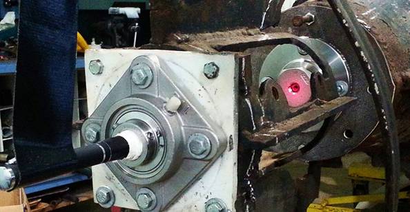
Monday, April 22, 2019: Got the bearings and flanges aligned and
marked on their respective mounting plates.
A little white spraypaint did the trick. Comes right off with Brake Clean. After taking this pic
I drilled eight holes and testfit these parts on the
submarine.
Bearings, flanges, tailcone bulkhead and propeller bearing mounting plate.
EVENING UPDATE: And this
is as far as I got with it today.
Everything's positioned in the submarine's empennage and seems like it's
going to be okay. I've got to shorten
the original motor mount at the white chalk line to locate the propeller
correctly in the fin cutout, but that was expected.
Propshaft and manifold installed for alignment
check.
Here's a video where I'm spinning the
prop by hand with the manifold in place.
Wednesday, April 24, 2019:
Check this out. Did a low-tech laser
alignment test on the propshaft bearings and it came
out pretty much spot-on. First of all, the
laser emitter isn't exactly aligned in the pointer housing, so I had to aim
it. Also, the pointer housing is smaller
than the 7/8" bearing aperture, so I wrapped it in a paper towel and
aligned it with a piece of Gorilla Tape. High tech, eh? J
Aft view: laser pointer
in propshaft bearing; aimed at tailcone
bearing.
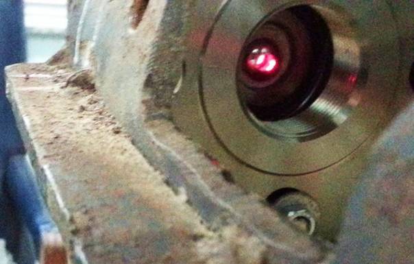
Laser pointer in propshaft bearing.
To center the tailcone bearing and flange AMAP, I put a reducer in the
flange and a small nut inside the reducer.
The bright spot of the laser beam passed through the nuts' center hole
and that red glow is scattered residual light bouncing off the reducer.
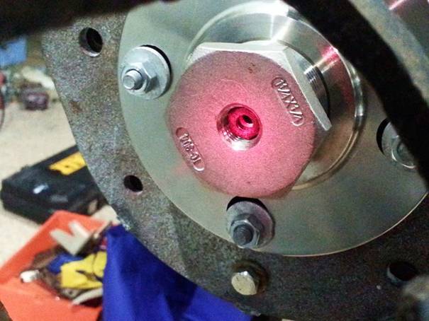
Residual laser light on tailcone bearing reducer.
This pic was taken at an angle from inside the
starboard salon window frame. As Rube
Goldberg as this test- device was, it still projected a laser dot to the
forward end of the pressure hull that was only off the longitudinal centerline
by an inch or so. That's pretty straight
for a rig like this and tells me that (1) my initial measurements and calculations
were good; and (2) there shouldn't be any difficulty doing the final (precise)
alignment of the propeller shaft when it comes time to install the motor.
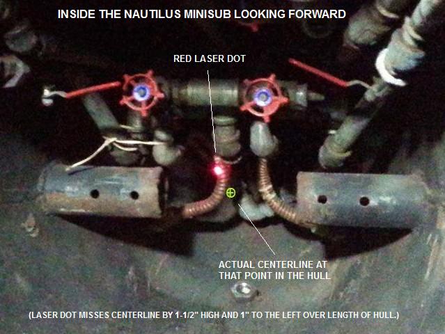
Laser dot falls nearly
dead center at forward end of pressure hull.
Next, I have to buy
all the correct hardware and fasteners; shorten the original MK motor mount to
properly locate the propeller bearing mounting plate; get the manifold adjusted
to the right length; and install the shaft seal. Then it will be time to do a wet bench test
of the seals' watertight integrity.
Coming right along and so far no insurmountable problems! AHEAD… FULL!!! J
UPDATE: Today I used the
torch and grinder to remove about 1/2" of steel from the point in the
empennage where the propeller bearing mounting plate resides. Now the propshaft
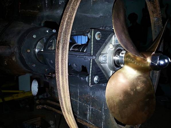
cap nut clears the rudder. Needs a
little fine adjustment but the dirty work is done; for today, anyway. ARGH!
J
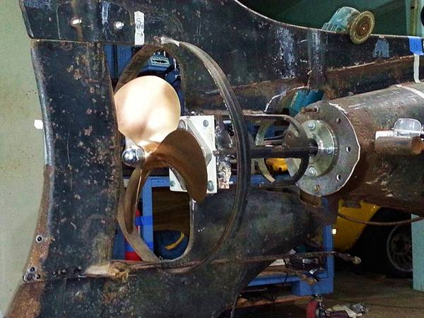
Propeller and rudder in
position with adequate clearance.
Saturday, April 27, 2019:
I decided I wanted a bit more clearance between the rudder and cap nut. Did a couple days surgery with the torch, big
and little Makita grinders, a carbide-tipped die grinder, and a Dremel. My new
OMNISQUARE tool came in handy repeatedly and works great! A big help!
Still, it was more
art than science as I gradually worked down to the desired level; stopping
along the way to mark high points with paint and squaring the surface by
grinding. All done by eyeball and
measurement.
Propeller bearing
mounting plate situated and squared with tailcone
bearing plate.
At this point, the
forward surface of the propeller bearing mounting plate is squared with aft
surface of the tailcone bearing mounting plate. Checked at eight locations around the prop
plate's circumference, we have a uniform distance of 12-3/8 inches. This was important to ensure the propeller
shaft passes through both bearings uniformly, and to determine the actual
length of the propeller shaft housing manifold.
12.375" all the way around or very close to it.
Here's a look at the
submarine's empennage mounts, cleaned up and ready to go. The tailcone plate
is mild steel; the propeller bearing plate is stainless steel.
stainless steel prop bearing
plate; original motor mount, shortened and squared; tailcone
bearing plate.
Next, I'll set it up
on the bench, assemble the manifold and shaft seal, and wet test them. If the seal is okay, then it's time to
install the drivetrain in the pressure hull. J
UPDATE TODAY: I'm questioning whether or not I should
assemble on the bench to wet-test the shaft seal; only to have to disassemble
and reassemble it all again in the boat.
I've already functionally tested the drivetrain
dry so I know it works. I'm pretty sure
I can install a mechanical shaft seal right the first time. I'm gonna go ahead
and install everything but the motor in the submarine. I can wet-test the seal by turning the shaft
in any of a number of ways not dependent on the actual motor. If the seal works, then I'll cut a dorsal
access hatch in the tailcone and install the motor,
guidance controls, and ballast system servo valves. This ought to save me at least a week or
more. Me likey! It shall be so! J
LAST GASP TONIGHT: VIDEO: Did a
test installation of the propshaft and housing
assembly into the submarine's original motor mount area. Everything lines up correctly and turns
nicely. I haven't lubed the bearings yet
but I'm pretty sure that "squeak" is a well-timed coqui
frog barking outside the open window a couple feet away. They've been going all night. J
So apparently this is
going to work and setting up for a wet bench test of the shaft seal would be a
waste of time.
Now I need to buy
eight 5/16th and four 1/4-20 fastener combos of the right length. And I've been waiting on a replacement for a
SS close nipple that arrived galled and useless; on the way and should be here
in a few days.
I made a neoprene
gasket years ago when I made the tailcone plate. I'm going to make another for the tailcone flange.
It's pretty thick stuff; I'll have to subtract its thickness from the
manifold length. But it will give us a
heavy duty "industrial grade" watertight rubber mount between the propshaft housing flange & bearing and the pressure
hull. Good seal and I'm expecting some
noise dampening. Could rubber mount the
propeller bearing mounting plate too, for that matter.
After I get it
running on the motor using hardware store fasteners, I'm going to weld some
1/4-20 threaded connectors in place and switch the cap screws over to stainless
steel button-head Allens. That way I'll be able to take off the
propeller bearing mounting plate without having to remove the outer hull plates
so I can get a backup wrench in there.
Sunday, April 28, 2019: Made the crude prototype of a reinforced
neoprene rubber mounting plate to replace the stainless steel propeller bearing
mounting plate I've used until now.
Concept seems feasible; I can see some improvements that can be
made. But this will help to inhibit the
migration of vibration and noise between the drivetrain
and the hull. Basically, the advantages
are shock absorption and sound deadening.
Since the tailcone cover plate, bearing, and flange will also be
rubber-mounted; this part of the drivetrain is rigged
for fairly quiet running. J
Tuesday, April 30, 2019:
I've decided not to do a preliminary installation and test of the shaft seal
because (1) it's not necessary; (2) I could damage the seal setting it up for a
"rehearsal"; and (3) I'll have to do it all again after the motor's
installed. I do believe I can install a
mechanical shaft seal right the first time.
I've done enough "spin tests" to be confident of how everything
is lining up and the numbers say it will fit.
I am proceeding to install the motor.
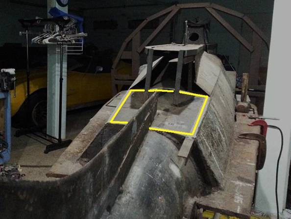
Yellow square marks
motor compartment hatch aperture.
Tape marks areas to be
cut.
As of last night and
this morning, I've got the hatch cut laid out and parts tape-marked for the
torch or plasma cutter. Gonna have rounded corners.
I'll scribe lines into the steel with an electric engraving tool and
remove the tape before I start cutting.
This will be the
first hull surgery of this magnitude since I first built the submarine. It's kind of an awesome feeling; what I'm
about to do. If I screw-up here, I could
wreck the boat. I'll just have to make
sure I don't screw-up, right? J
Wednesday, May 01, 2019: I'm not into computer design, 3D printing, or
any of that. I am totally "by
hand" and "blacksmith style"; but that's all I've ever
needed. Here's a simple concept sketch
of how the hatch will be built. (And I usually don't go into this much
detail. J )
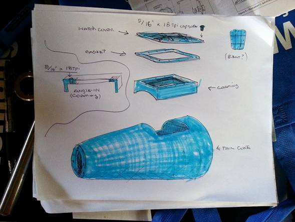
Nautilus Minisub motor compartment hatch concept sketch.
The vertical sides of
the angle-iron coaming will also serve as the walls
at the top of the aft ballast tanks. The
"L" of the angle iron will face inboard; serving as a flat flange for
the hatch cover and gasket. The flange
fastener holes will be drilled and tapped for 5/16" cap screws.
I was thinking of
using a flat hatch with a 12-bolt pattern.
But then I thought about welding on some external stiffeners for
strength and when I drew it out I realized all I'd need is eight bolts.
Now all I have to do
is measure the boat, make cardboard templates, cut the steel, and weld it
up.
For me, it's all
about minimal graphics and maximal fabrication.
I avoid "analysis paralysis" by getting right into making
parts ASAP. Works for me. J
Thursday, May 02, 2019: I spend a lot of time looking at the sub and
thinking about what I'm doing to it; new ideas arise that way. It was the same with my motorcycle. I'd ride it to the waterfront end of First
Street in Benicia and kick back in the shade enjoying a cold beer while
contemplating what I wanted to do to it next.
I remember one time some girls drove by and yelled, "Park it and
look at it!" LOL! Nobody wants to understand. J
Anyway, right now
with the submarine's 3/16" steel tailcone plate
and the 2X2" bell chamber nipple; the manifold is exactly 1/8" too
long to fit. I can rectify that when I
tighten the nipple into the seal chamber bell and if that doesn't work I have
ordered a 2" close nipple that will
give me all the room I need, lengthwise.
But then, there's the
added thickness of the flange and tailcone-plate
gaskets; another half inch all together.
That would make the assembly 5/8" too long.
I was thinking
about how to handle that problem when it
occurred to me; why not make the tailcone plate out
of reinforced rubber? It's only
1/16" thicker than the steel; plus it eliminates the thickness of both
gaskets. I can make that fit without
bending it.
But what about depth
pressure defeating a rubber tailcone plate? We're talking about making part of the
pressure hull out of rubber and that sounds kinda
crazy the first time you hear it. Okay,
maybe the second. But it makes sense
when you think about it.
The diameter of the
flange is only about 1/16th of an inch smaller than the aperture inside the
drilled and threaded tailcone boss; and the square
bearing housing takes up most of the room on the other side. The tailcone boss
supports the entire outer periphery of the plate and if I use wide washers (or
a single toroidal band of sheetmetal
drilled with eight holes) almost all of
the rubber surface will be backed-up by steel.
And that which isn't
directly supported is too thick, hard, and reinforced to pass through any tiny
(crack-like) gap that might exist; even at far greater depths and pressures
than this boat will ever be asked to endure.
Considering the way
the assembly is built and attached to the submarine, and the strength
characteristics of the material I'm using; I do believe a rubber tailcone plate is feasible and will greatly reduce
perceived vibration and noise migrating from the drivetrain
to the hull. Worth a try, anyway.
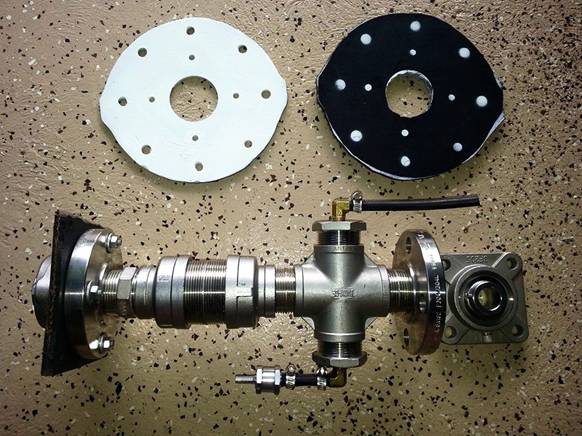
White (painted) steel tailcone cover plate; black neoprene tailcone
cover plate; propshaft manifold with mechanical shaft
seal and pressure compensation; tailcone bearing.
So today I laid out
and cut a rubber tailcone plate from 1/4"
fiber-reinforced neoprene that was once part of a conveyor belt at the local
sugar mill; traced the metal cover with an ink pen and cut it out with a
box-cutter.
TECH TIP: Cutting
rubber like this can be extremely difficult because it has a very high drag
coefficient. Getting a bare blade
through it is a fight every step of the way.
But use a little DAWN Detergent
or the like to lubricate the rubber and your blade will slide through much
easier.
Then I laid the plate
on the cutout rubber facsimile and shot a little white paint to re-mark the
holes. And if I use the metal plate, the
inside of the motor compartment is going to be white anyway; so all's well.
After the paint
dries, it's time to put holes in it.
I've got some punches I use for making bolt holes in the collar gaskets for deep sea
diving helmets; I'll try that. If not,
there's always that funky little Ryobi drill press I bought. It ain't a
workhorse but I'm pretty sure it can cut holes in rubber. Maybe.
Worth a try, anyway. J
Friday, May 03, 2019: When the time comes to test the Nautilus Minisub, I could drive it to the harbor. Or I could ask my friend (who owns a crane)
to put it in our 32 x 16 x 4.5' pool. If
I rig a "dog run" cable (with stops) lengthwise over the pool from
our shipping container to our forklift, I can drive the boat about 10 feet
without any chance of poking a hole in the liner. With foam rubber boots on the keel, we can
submerge safely on ballast, too. And if
I center and secure the boat to something ashore in a manner where it can't
possibly break loose (steel cables to my 5 ton forklift) I don't see any reason
we can't push the drivetrain to cruising speed and
higher.
(And as I write that, I'm sitting here visualizing what it will be like
to be in the sub or the immediate area, when that boat is in the center of our
pool with the motor cranked up to collision speed full. I get stoked just thinking about it.)
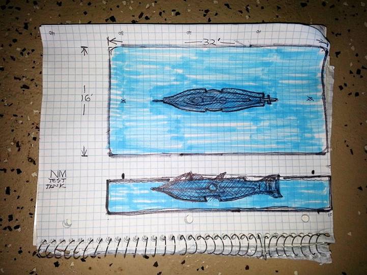
I drew this with it
sitting on my lap; didn't try too hard to get the lines straight but you get
the idea, right? J
There will be plenty
of room for the sub and crew in the pool.
This way I can get everything dialed in and working right before I take
it to the ocean. Plus, if I ever want to
train anyone how to pilot the Nautilus Minisub, this
would be a safe and convenient way to do it.
Not to mention the fact that it's going to be an outrageously fun pool
toy to play with. J
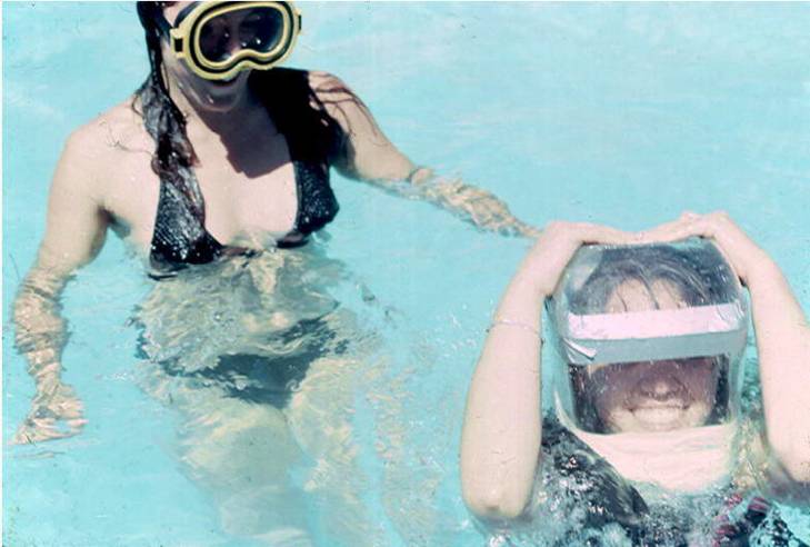
Lynn Regan tends
Christine "Steenie" Nelson as she submerges
in a homemade air-supplied diving helmet for the first time in her life. The smile says it all. J
In Benicia back in
the 1980's, we were letting our friends play with homemade rebreathers
made from soda bottles; and air-supplied diving helmets made from an ink-pen
display Lynn salvaged from the dumpster at Longs
Drugs. From those humble (but fun!)
beginnings, we've gone to training people how to dive a 20,000 Leagues rig in
our pool and soon we'll be able to operate the submarine in there, too. Wow.
That even blows MY mind.
LOL! J
MORE TO FOLLOW…